I did make one of these, but I don't seem to have a very good schematic still around.
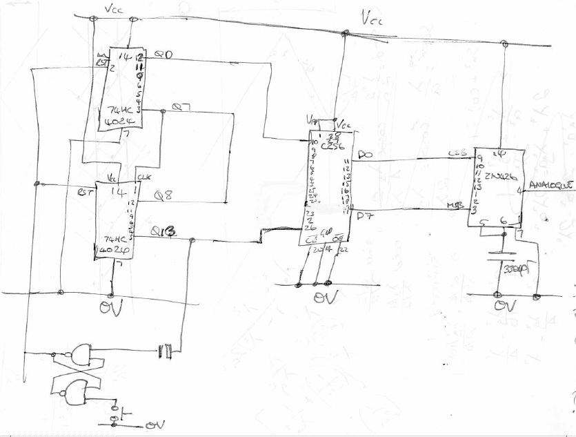
Here's a JPG of the circuit diagram I do have (click to enlarge);
The circuit is fairly simple to understand.
There is an 8k EPROM holding the sampled 'ah-yeah'. Two 8bit binary counters are chained together and count up through the address lines (2^13). The data out of the PROM then drive a D-to-A converter. In the circuit I built, the output of the D-to-A drives some type of power op-amp and a small loudspeaker. I have in the past hooked mine up to the input of my hi-fi to annoy my housemates.
The counters have a reset line (coupled together) which is driven from an SR latch. When the line going into address line Q13 of the EPROM goes high it causes the output of the SR latch to drive the two counters to reset. The output of the SR latch will stay low, holding the counter at 0x0000 until the (momentary) push-button is pressed. Once pressed and released, the momentary button will toggle the state of the SR latch, enabling the counter to run again (cycling through the memory of the EEPROM.
Pressing the push-button at any time causes a reset, allowing the 'ah-yeah' to be halted, or even an effect like 'ah-ah-ah-ah-ah----ah-yeah' to be created.
| 74HC4024 | 8 bit binary counter - 2off |
| 27C256 | 8k EEPROM ... I know there's a joke at Steves expense in here somewhere :-/ |
| ZN426 | 8bit A-to-D converter Probably can't get 8bit anything anymore - ED! |
| Switch | Momentary, push to close button |
| NAND | Some type of QUAD NAND |
Circuit Diagram